


Power Transient Signal Measurement
Highlights
Microsecond-to-nanosecond waveform capture for insulation diagnostics and power quality
For substation switching/lightning overvoltages, high-speed-rail transients, partial discharge pulses and power-quality disturbances. Wideband RC dividers, UHF antennas and high-frequency Rogowski coils combined with ≥10 MS/s synchronous acquisition capture transient waveforms from microseconds down to nanoseconds, enabling overvoltage front, PD spectrum and harmonic/flicker/sag analysis.
Extremely wide frequency span: from power frequency to lightning and nanosecond partial-discharge pulses spans more than ten orders of magnitude — no single band can cover it all.
High-potential, strong-EMI environment: substations and high-speed-rail traction networks carry hundreds of kilovolts and strong electromagnetic fields, demanding strict insulation, shielding and isolation.
Sporadic, non-repeatable transients: switching overvoltages, lightning overvoltages and partial discharges are occasional events, requiring long-term monitoring and reliable triggering to capture.
Multi-point time traceability: waveforms from different points must be aligned on a µs-level time base to invert propagation paths and locate faults.
System architecture
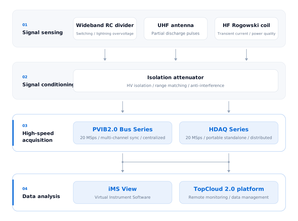
Power transient signal measurement system architecture: a wideband RC divider (switching/lightning overvoltage), UHF antenna (partial discharge pulses) and HF Rogowski coil (transient current/power quality) pass through an isolation attenuator into the PVIB2.0 Bus Series (centralized) and HDAQ Series (distributed), with data going to iMS View Virtual Instrument Software and the TopCloud 2.0 platform.
Related equipment
Technical questions
How should series and module sampling specifications be distinguished for power transients?
PVIB2.0 series sampling, the HDAQ series figure and the NDAQ-20024 per-channel specification are listed separately. Select a module for the signal; a series maximum does not describe every module.
Context and configuration
The power scenario includes switching or lightning overvoltages, partial discharge and power quality. Check the measurement chain for each task.
Specifications and conditions
- PVIB2.0 Bus Series · Sample rate 100KSps–1GSps
- HDAQ Series · Sample rate 2MSps
- NDAQ-20024 · Measurement Performance · Max Sample Rate 200 KSps
Application limits
A series sampling range alone does not establish that one module covers every task or a particular time-resolution requirement.
Why should sample rate, bandwidth and input range be checked separately?
Sample rate, analogue bandwidth and input range are separate selection fields. For the NDAQ-20024, check per-channel sampling, dynamic-performance bandwidth and analogue input range together.
Context and configuration
Signals pass through sensing and conditioning before reaching the acquisition module. Module specifications do not replace the operating limits of the front end.
Specifications and conditions
- NDAQ-20024 · Measurement Performance · Max Sample Rate 200 KSps
- NDAQ-20024 · Analog Performance · Bandwidth 100 kHz
- NDAQ-20024 · Measurement Performance · Range ±10 V、±5 V、±1 V、±500 mV
Application limits
Do not substitute sample rate for bandwidth or equate the measured quantity before conditioning with the module input range.
Related specifications
How do sensing, conditioning and acquisition connect in power measurements?
The architecture distinguishes wideband RC dividers, UHF antennas and high-frequency Rogowski coils by measurement task. Isolation and attenuation precede PVIB2.0 or HDAQ acquisition, with data sent to iMS View and TopCloud.
Context and configuration
Overvoltage, partial-discharge pulses and transient current use different front ends. Specify the sensor, conditioning and acquisition-module combination.
Application limits
A system diagram does not mean every model includes every front-end function, and a series sampling maximum is not the bandwidth of the complete chain.
Related specifications
How should HDAQ and PVIB2.0 channel configurations be read for multi-channel power measurements?
The channel figures below describe series or system configurations. After defining measurement points, check the actual modules, per-module channels, synchronisation and transport configuration.
Context and configuration
HDAQ and PVIB2.0 provide modular measurement arrangements, while iMS View handles analysis and presentation in this scenario.
Specifications and conditions
- HDAQ Series · Channels up to 24
- PVIB2.0 Bus Series · Synchronous channels per unit 4–96
Application limits
A series channel range does not describe every individual module, and a software role must not be presented as hardware sampling performance.